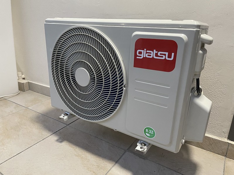
In a mini-split system, the liquid and gas refrigerant do not share the same chamber. The system operates on the principle of heat transfer, where the refrigerant captures heat from the air in one location and transfers it to another. The condenser/compressor unit, or “heat pump,” uses liquid refrigerant to capture heat from the air.
Understanding the Refrigerant Flow in a Mini-Split System
-
Liquid Line: The liquid line carries the refrigerant in its liquid state from the condenser to the evaporator. This line is typically insulated to prevent heat gain, ensuring the refrigerant remains in a liquid state.
-
Suction Line: The suction line carries the refrigerant in its gaseous state from the evaporator to the compressor. This line is typically not insulated, allowing for heat loss and ensuring the refrigerant remains in a gaseous state.
-
Refrigerant Separation: The liquid and gas refrigerant lines are completely separate from each other, with no shared chambers or components. This separation is crucial for the proper functioning of the mini-split system.
Cooling Mode Operation
-
Refrigerant Capture: When the mini-split system is in cooling mode, the condenser/compressor unit uses the liquid refrigerant to capture heat from the air.
-
Refrigerant Transfer: The extremely cold liquid refrigerant is then transferred to a series of coils located inside the air handler.
-
Heat Transfer: As the air handler runs, it draws hot air from the room. This air flows through the cooled refrigerant coils, and the heat from the air is transferred to the refrigerant.
-
Refrigerant Compression: The refrigerant, now in a gaseous state, passes through the compressor, which drastically increases its temperature.
-
Heat Dissipation: The heated refrigerant is then transferred to the air handler, where it releases the heat, and the cycle repeats.
Heating Mode Operation
-
Refrigerant Capture: When the mini-split system is in heating mode, the process is reversed. The condenser/compressor unit uses the gaseous refrigerant to capture heat from the air.
-
Refrigerant Transfer: The heated refrigerant is then transferred to the air handler, where it releases the heat.
-
Heat Transfer: The air handler draws in cold air from the room and passes it over the heated refrigerant coils, transferring the heat to the air.
-
Refrigerant Condensation: The refrigerant, now in a liquid state, is then transferred back to the condenser/compressor unit, where the cycle repeats.
Importance of Refrigerant Line Temperatures
-
Liquid Line Temperature: The liquid line should be colder than the saturation temperature of the refrigerant. If the liquid line is warmer, it indicates a restriction in the line, causing the compressor to work harder and reducing the system’s efficiency.
-
Suction Line Temperature: The suction line should be warmer than the saturation temperature of the refrigerant. If the suction line is colder, it indicates a restriction in the line, causing the compressor to work harder and reducing the system’s efficiency.
-
Temperature Monitoring: Regularly monitoring the temperatures of the liquid and suction lines is crucial for maintaining the mini-split system’s efficiency and longevity.
In summary, the liquid and gas refrigerant in a mini-split system do not share the same chamber. The refrigerant lines are designed to carry either liquid or gas refrigerant, and they are separate from each other. Maintaining the correct temperature difference between the liquid and suction lines is essential for the system’s optimal performance and energy efficiency.

