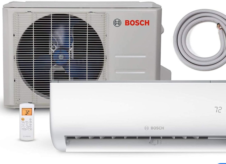
Troubleshooting a Bosch inverter board can be a complex task, but with the right approach and understanding of the underlying technology, it can be a manageable process. This comprehensive guide will walk you through the step-by-step process of testing a Bosch inverter board, providing you with the technical details and expert-level insights to ensure a successful diagnosis and repair.
Checking the Inverter Compressor Windings Resistance
The first step in testing a Bosch inverter board is to check the resistance of the inverter compressor windings. Inverter compressors, unlike traditional compressors, have three windings instead of two. It is crucial that all three windings have the exact same resistance, as any variation of more than 1 ohm can prevent the compressor from running correctly.
To check the windings resistance:
- Locate the compressor terminals on the inverter board and use a digital multimeter to measure the resistance between each pair of terminals.
- Compare the resistance readings for all three pairs of terminals. The readings should be identical, within a tolerance of 1 ohm.
- Refer to the manufacturer’s specifications to determine the expected resistance value for the compressor windings. This information can typically be found in the service manual or by contacting Bosch’s technical support.
- If the resistance readings vary by more than 1 ohm, the compressor may need to be replaced, as the windings are likely damaged or imbalanced.
Verifying Input Voltages

The next step in testing the Bosch inverter board is to ensure that it is receiving the correct input voltages. The inverter board requires two separate voltage inputs:
- 120 VAC Main Power Supply: This is the primary power source for the inverter board, providing the necessary voltage to drive the compressor.
- 4 to 6 VDC Control Voltage: This low-voltage control signal comes from the main control board (or “Muthaboard”) and is used to communicate with and control the inverter board.
To check the input voltages:
- Use a digital multimeter to measure the voltage at the appropriate terminals on the inverter board, ensuring that both the 120 VAC and 4-6 VDC inputs are present and within the expected ranges.
- If either of the input voltages is missing or out of range, you will need to backtrack and troubleshoot the power supply or control board to identify and resolve the issue.
- It is crucial to make all voltage measurements with the system fully connected, as disconnecting components can sometimes cause voltage readings to be inaccurate.
Manually Testing the Inverter Board
In addition to checking the compressor windings and input voltages, you can also manually test the inverter board itself using a multimeter. This process involves checking for continuity and resistance in the various components on the board, which can help identify any issues with the board’s circuitry.
To manually test the inverter board:
- Disconnect the inverter board from the refrigerator and remove it from the system.
- Use a multimeter to check for continuity between various points on the board, ensuring that there are no open circuits or short circuits.
- Measure the resistance of individual components, such as capacitors, transistors, and diodes, to ensure they are within the expected ranges.
- Refer to the manufacturer’s service manual or schematics to identify the expected resistance and continuity values for the various components on the inverter board.
- If you identify any components that are out of specification, the inverter board may need to be replaced.
Importance of Replacement Part Compatibility
When testing and replacing a Bosch inverter board, it is crucial to ensure that the replacement part is compatible with your specific refrigerator model. In the case of Bosch refrigerators, the inverter signal code is a critical factor to consider.
The original Bosch inverter board may have a signal code of 519306098, which corresponds to a “Frequency” control signal. However, a replacement inverter board may have a signal code of 519306214, which corresponds to a “Drop-in” control signal. It is unclear whether the “Drop-in” signal is fully backward compatible with the “Frequency” option.
To ensure a successful replacement:
- Carefully note the signal code of your original inverter board.
- Verify that the replacement part you are considering has the same or a compatible signal code.
- If the signal codes do not match, it is recommended to contact Bosch’s technical support or a qualified appliance repair professional to determine the appropriate replacement part.
Using an incompatible inverter board can lead to issues with the refrigerator’s operation and may even cause further damage to the system.
Conclusion
Testing a Bosch inverter board requires a methodical approach and a deep understanding of the underlying technology. By following the steps outlined in this comprehensive guide, you can effectively diagnose and troubleshoot issues with the inverter board, ensuring a successful repair and the continued reliable operation of your Bosch refrigerator.
Remember to always refer to the manufacturer’s specifications, service manuals, and technical resources when working on Bosch appliances, and consider seeking the assistance of a qualified appliance repair professional if you encounter any complex or unfamiliar issues.
