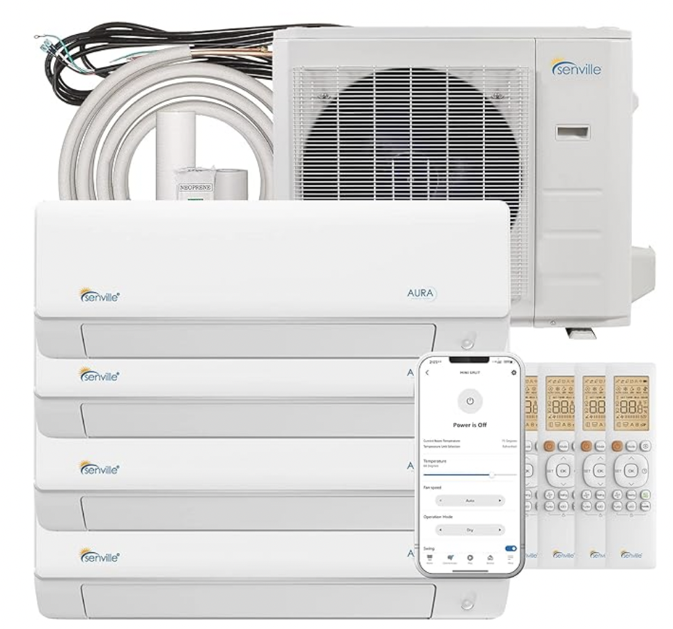
Troubleshooting a Senville inverter board can be a complex task, but with the right approach and tools, you can effectively diagnose and address any issues. This comprehensive guide will walk you through the step-by-step process of testing a Senville inverter board, providing you with the technical details and expert-level insights to ensure a successful DIY repair.
Checking the Voltage
The first step in testing a Senville inverter board is to check the voltage of the unit. This can be done using a multimeter, a versatile tool that allows you to measure various electrical parameters. By checking the voltage, you can determine whether the problem lies with the inverter board or the compressor.
To check the voltage, follow these steps:
- Ensure that the unit is powered on and the circuit breaker is in the “on” position.
- Locate the terminals or connectors on the inverter board that provide power to the compressor.
- Set your multimeter to the appropriate voltage range, typically 200-300 volts for a Senville inverter board.
- Carefully touch the multimeter probes to the terminals or connectors, ensuring a secure connection.
- Observe the voltage reading on the multimeter. If the voltage is within the expected range, the issue may be with the compressor. If the voltage is significantly lower or absent, the problem is likely with the inverter board.
Testing the PCB Board

Another way to test the Senville inverter board is by using a tester with LED lights. This method involves disconnecting the wires from the compressor and connecting them to the bulbs on the tester.
- Locate the outdoor PCB (Printed Circuit Board) within the unit.
- Disconnect the wires that connect the PCB to the compressor.
- Connect the same wires to the LED bulbs on your tester.
- Observe the behavior of the bulbs:
- If the bulbs glow, it indicates that the outdoor PCB is passing electricity to start the compressor.
- If the bulbs stop glowing, it suggests that the compressor is not starting, and the problem is likely with the compressor.
This simple test can help you quickly identify whether the issue is with the PCB or the compressor.
Testing the PCB with an Analyzer
For a more comprehensive analysis of the Senville inverter board, you can use an analyzer. This specialized tool allows you to test the PCB and understand whether the problem is with the PCB or the compressor.
- Locate the same wires you used with the LED tester and connect them to the analyzer.
- Refer to the analyzer’s instructions to interpret the readings and determine the root cause of the issue.
- The analyzer will provide detailed information about the PCB’s performance, helping you identify any malfunctioning components or connections.
Checking the Indoor PCB
If the unit does not respond to the remote control, the issue may lie with the indoor PCB. To test the indoor PCB, follow these steps:
- Locate the indoor unit and access the electronic control box.
- Inspect the indoor PCB for any visible signs of damage or wear.
- Check the connections between the indoor PCB and the remote control.
- If the unit responds to the remote, the display board is working correctly, and the issue is likely with the indoor PCB.
Disassembling the Outdoor Unit
To thoroughly test the Senville inverter board, you’ll need to disassemble the outdoor unit. This process involves several steps:
- Unfix the hooks and open the electronic control box cover.
- Remove the screws on the electronic control board and turn it over.
- Pull out the connectors and remove the electronic control board.
- Remove two screws and two connectors to detach the inverter control board.
Once the inverter control board is accessible, you can proceed with further testing and inspection.
Checking Connectors and Wires
After disassembling the outdoor unit, carefully inspect the connectors and wires for any damage or loose connections. Tighten any loose connections and replace any damaged components to ensure proper electrical continuity.
- Visually inspect all connectors and wires for signs of wear, corrosion, or damage.
- Use a multimeter to test the continuity of the wires and connections.
- Tighten any loose connections and replace any damaged components.
Testing the Compressor
Finally, after testing the inverter board and the connectors, you’ll need to test the compressor itself. Use a multimeter to check the voltage and current of the compressor.
- Locate the compressor terminals or connectors.
- Set your multimeter to the appropriate voltage and current ranges.
- Measure the voltage and current of the compressor.
- If the compressor is not working correctly, it will need to be replaced.
Remember, testing and repairing a Senville inverter board requires technical knowledge and experience. If you’re not comfortable performing these tasks, it’s recommended to consult a professional HVAC technician.
References:
