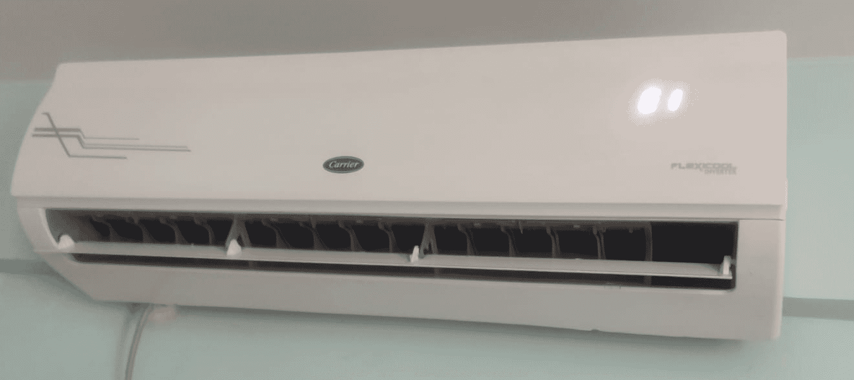
Troubleshooting a Carrier inverter board can be a complex task, but with the right approach and tools, it can be done effectively. This comprehensive guide will walk you through the step-by-step process of testing a Carrier inverter board, providing you with the technical details and expert insights needed to diagnose and resolve any issues.
Checking the DC Voltage between C+ and C-
The first step in testing a Carrier inverter board is to check the DC voltage between the C+ and C- terminals. This is a crucial step in identifying any potential issues with the board’s power supply.
- Isolate the Compressor Terminals: Begin by removing and isolating the compressor terminals from the inverter board.
- Turn on the Power: With the compressor terminals disconnected, turn the power back on to the equipment.
- Set the System to Transistor Check Mode: Place the system into transistor check mode, typically referred to as Setting 2 – 28.
- Measure the Voltage: Using a multimeter, check for a balanced output voltage between all three compressor wires. The voltage should be within the specified range provided in the equipment’s service manual.
- Analyze the Readings: If the voltage readings are not within the expected range, it could indicate a problem with the power supply or the inverter board itself. Further investigation will be required to pinpoint the issue.
Checking for Earth Leakage

Some Carrier inverter board designs feature a designated grounding terminal that can be used to test the internal components of the board for any earth leakage issues.
- Locate the Grounding Terminal: Refer to the equipment’s service manual to identify the grounding terminal on the inverter board.
- Measure the Resistance: Use a multimeter to measure the resistance between the grounding terminal and the board’s internal components. There should be no continuity, indicating a lack of earth leakage.
- Interpret the Results: If the multimeter detects continuity between the grounding terminal and the board’s components, it could signify an earth leakage problem, which may require the replacement of the inverter board.
Checking for Continuity
Ensuring proper continuity between the compressor terminals and the inverter board is another crucial step in the testing process.
- Disconnect the Compressor: Isolate the compressor terminals from the inverter board.
- Measure the Continuity: Use a multimeter to check for continuity between the compressor terminals and the corresponding connections on the inverter board. There should be no continuity between any of the terminals and ground.
- Analyze the Readings: If the multimeter detects continuity between the compressor terminals and ground, it could indicate a problem with the compressor or the wiring, which may require further investigation or replacement.
Checking the Communication Circuit
The communication circuit of the Carrier inverter board is responsible for determining the output frequency and timing. While this circuit is not covered in detail in this article, it is an essential component of the board’s operation and should be tested as per the equipment’s service manual.
- Refer to the Service Manual: Consult the equipment’s service manual for specific instructions on how to test the communication circuit of the Carrier inverter board.
- Measure the Signals: Use a multimeter or an oscilloscope to measure the signals and voltages within the communication circuit, as directed by the service manual.
- Interpret the Readings: Analyze the measured values and compare them to the expected specifications. Any discrepancies may indicate a problem with the communication circuit, which may require further troubleshooting or replacement of the inverter board.
Additional Considerations
When testing a Carrier inverter board, it’s essential to keep the following points in mind:
- Service Manual Guidance: Always refer to the equipment’s service manual for specific instructions and guidelines on testing the inverter board. The information provided in this article may not be accurate for all Carrier models, as the components and testing procedures can vary.
- Safety Precautions: Exercise caution when working with electrical equipment, as inverter boards can pose a risk of electric shock. Ensure that you follow all safety protocols and wear appropriate personal protective equipment (PPE).
- Replacement Parts: If the testing process reveals a problem with the inverter board, it’s crucial to replace it with a genuine Carrier part to ensure proper functionality and compatibility with the equipment.
- Professional Assistance: If you are unsure about any aspect of the testing process or encounter issues that you cannot resolve, it’s recommended to seek the assistance of a qualified HVAC technician or service provider.
By following the steps outlined in this comprehensive guide and adhering to the equipment’s service manual, you can effectively test and troubleshoot a Carrier inverter board, ensuring the proper operation of your HVAC system.
