As a DIY user with advanced hands-on expertise, testing a Lennox inverter board can be a complex yet rewarding task. This comprehensive guide will walk you through the step-by-step process, providing technical specifications and detailed instructions to ensure a successful diagnosis and troubleshooting of your Lennox inverter board.
Safety First: Preparing for the Test
Before delving into the testing process, it’s crucial to prioritize safety. Ensure that the unit is turned off and disconnected from the power source. Remove the compressor terminals to avoid touching the cabinet or grounding out, which could lead to potential electrical hazards.
Checking the DC Voltage
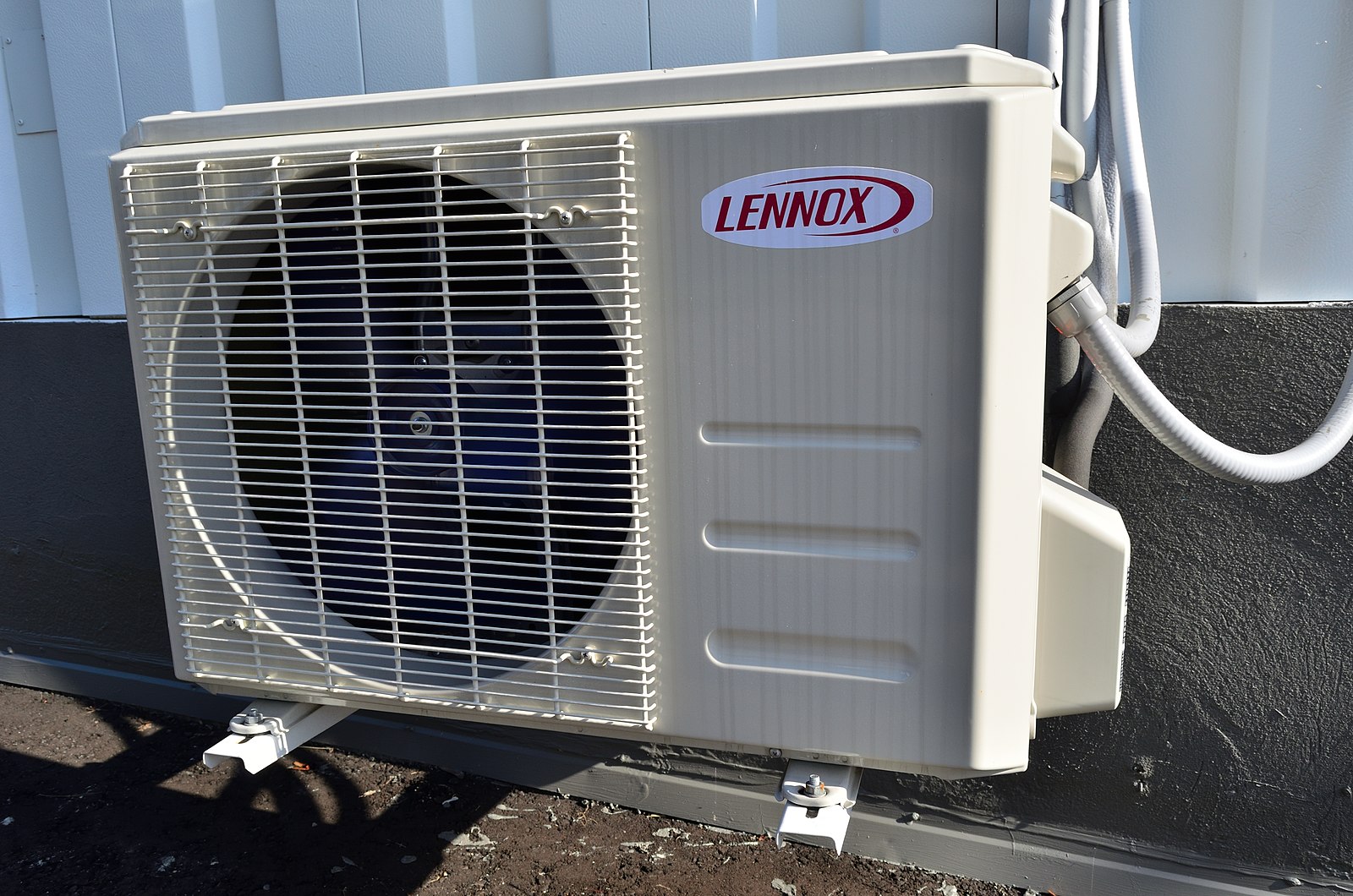
 Image source: Lennox Ac by Raysonho
Using a multimeter, measure the DC voltage between the C+ and C- terminals on the inverter board. The expected reading should fall within the specifications provided in the Lennox service manual. This step helps you identify any discrepancies in the DC power supply, which could be a potential source of the issue.
Entering Transistor Check Mode
Turn the power back on to the equipment and place the system into transistor check mode, typically referred to as Setting 2 – 28. This mode allows you to assess the performance of the transistors on the inverter board, which are responsible for converting the DC power into the necessary AC waveform for the compressor.
Verifying Output Voltage
With the system in transistor check mode, use a multimeter to check the output voltage between all three compressor wires. The readings should be within the specifications outlined in the Lennox service manual. This step helps you identify any imbalances or irregularities in the output voltage, which could indicate a problem with the inverter board’s power conversion capabilities.
Testing for Ground Leakage
Some Lennox inverter board designs feature a designated grounding terminal. Utilize this terminal to test for any earth leakage associated with a potential failure. This step helps you identify any issues related to the board’s grounding or insulation integrity.
Exploring the Communication Circuit
It’s important to note that this guide does not cover the communication circuit of the inverter board, which is responsible for determining the output frequency. This aspect of the inverter board’s operation will be addressed in a future technical tip.
Unique Perspective: Understanding the Principles
When testing a Lennox inverter board, it’s essential to have a solid understanding of the basic principles behind these boards. By developing this understanding, you can build confidence in diagnosing and troubleshooting issues, even if you’re not an expert in electronics. Remember, safety should always be the top priority, and it’s crucial to double-check the service manual for the specific equipment you’re working on.
Technical Specifications and Hands-on Approach
DC Voltage Measurement
- Use a digital multimeter with a minimum accuracy of 0.1% and a resolution of 0.01V.
- Measure the DC voltage between the C+ and C- terminals on the inverter board.
- The expected DC voltage should be within the range specified in the Lennox service manual, typically between 310-390VDC.
- Ensure the multimeter is set to the appropriate DC voltage range to obtain an accurate reading.
Transistor Check Mode
- Locate the mode selection switch or jumper on the inverter board, typically labeled as “Setting 2 – 28” or similar.
- Engage the transistor check mode by setting the switch or jumper to the appropriate position.
- This mode will activate the transistors on the inverter board, allowing you to test their functionality.
Output Voltage Verification
- Use a digital multimeter with a minimum accuracy of 0.1% and a resolution of 0.1V.
- Measure the output voltage between the three compressor wires (U, V, and W) on the inverter board.
- The expected output voltage should be within the range specified in the Lennox service manual, typically between 0-230VAC.
- Ensure the multimeter is set to the appropriate AC voltage range to obtain accurate readings.
Ground Leakage Testing
- Locate the designated grounding terminal on the inverter board, if available.
- Use a digital multimeter or an insulation tester to measure the resistance between the grounding terminal and the cabinet or other grounded surfaces.
- The expected resistance should be within the range specified in the Lennox service manual, typically less than 1 ohm.
- If the resistance is higher than the specified value, it may indicate a ground leakage issue on the inverter board.
Remember, always refer to the Lennox service manual for the specific technical specifications and testing procedures for your Lennox equipment. Following the manufacturer’s guidelines is crucial to ensure accurate diagnosis and safe troubleshooting.
