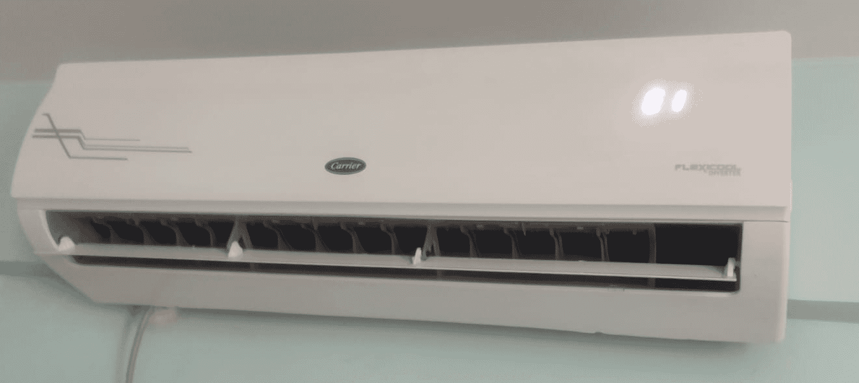
Carrier zone controllers are essential components in modern HVAC systems, providing precise control and optimization of airflow and temperature in individual zones. To effectively utilize a Carrier zone controller, it is crucial to follow a comprehensive installation, start-up, and configuration process. This guide will delve into the technical details and step-by-step instructions to ensure your Carrier zone controller operates at its full potential.
Installation and Connectivity
- Proper Wiring and Connections: Ensure that the zone controller and the air handler controls are properly connected to the CCN (Carrier Comfort Network) bus. This communication link is essential for the system to function correctly.
- Duct Design Considerations: Implement a good duct design with sufficient straight duct at the inlet of the terminal box. This design feature is recommended for optimal airflow and pressure-independent control.
- Sensor Placement: Strategically place the wall-mounted, field-supplied space temperature sensor (SPT) to accurately monitor zone temperature changes and satisfy zone demand. For stand-alone applications or those with heat, connect a field-supplied supply air temperature (SAT) sensor to monitor the temperature of the air delivered by the air terminal.
Network Addressing and Configuration

- Default Address: Each Carrier zone controller will initially default to an address of 0, 140 when its application software is first loaded.
- Unique Addressing: Since multiple controllers will be on the same bus, it is crucial to assign a unique address to each controller before the system can operate correctly. This ensures proper communication and integration within the network.
- Address Assignment: The assignment of controller addresses can be performed through software using the Address Search function of the Carrier Network Service Tool. This tool allows you to change the zone controller address from the default 0, 140 to a valid system address within 15 minutes.
- Addressing Considerations: When assigning addresses, keep in mind that the zone controller address can be changed from 0, 140 to 239, 239 for a period of 15 minutes, during which the address can be set to a valid system address.
Linkage and Standalone Operation
- Linkage for Non-Carrier Devices: The Comfort System AirManager (CSAM) or the CC6400 supports linkage for non-Carrier devices or air handlers. This feature allows the zone controller to integrate and communicate with a wider range of HVAC components.
- Standalone Operation: The zone controller can function as a standalone device by installing a primary supply air sensor. It monitors the differential pressure from an airflow pickup mounted on the terminal box and compares the resulting signal to an airflow set point to provide pressure-independent control of the air passing through the terminal.
Sensor Integration and Configuration
- Space Temperature Sensor (SPT): The zone controller is connected to a wall-mounted, field-supplied SPT sensor to monitor zone temperature changes and satisfy zone demand.
- Supply Air Temperature (SAT) Sensor: For stand-alone applications or applications with heat, the zone controller must be connected to a field-supplied SAT sensor to monitor the temperature of the air delivered by the air terminal.
- Network Service Tool Integration: Carrier’s Network Service Tool can be connected to the system at the SPT sensor if CCN communication wiring is run to the SPT sensor. This tool allows you to adjust set points, set operating parameters, and fully configure the zone controller or any device on the system.
Pressure-Independent Control
- Airflow Monitoring: The zone controller monitors the differential pressure from an airflow pickup mounted on the terminal box, comparing the resulting signal to an airflow set point.
- Pressure-Independent Operation: By using this pressure-independent control, the zone controller can provide precise control of the air passing through the terminal, ensuring optimal airflow and temperature regulation.
- Airflow Set Point: The zone controller adjusts the terminal box damper position to maintain the desired airflow set point, ensuring pressure-independent operation and efficient air distribution.
Troubleshooting and Maintenance
- Diagnostic Tools: Utilize the Carrier Network Service Tool to diagnose any issues, adjust set points, and configure the zone controller or other system components.
- Regular Maintenance: Perform regular maintenance on the zone controller, including cleaning, calibration, and verification of sensor readings, to ensure optimal performance and longevity.
- Firmware Updates: Stay up-to-date with the latest firmware updates for the zone controller, as they may include bug fixes, performance enhancements, and new features.
By following the detailed instructions and technical specifications outlined in this guide, you can effectively install, configure, and maintain your Carrier zone controller for optimal HVAC system performance and energy efficiency.
